Workshop and On-site Servicing, Maintenance, Servicing & PAT Testing
Sound Services supply and maintain most audio products by Monacor, IMG Stageline, Adastra, QTX, Chord, Citronic, Eagle, W Audio, Soundlab, Clever Acoustic and other leading brands
Sound Services offer a local PAT (testing) service – we are able to test and certify individual items or test, register and certify all of your portable electrical appliances
Circuit Diagrams, Service Data and Manuals
Sound Services can supply circuit diagrams and other service & technical data on many of the PA products and sound systems – covering products by Monacor, IMG Stageline, Adastra, QTX, Chord, Citronic, Eagle, W Audio, SoundLab, Clever Acoustics, Toa, Carlsbro and Pulse and other respected manufacturers
We are continually building our library of circuit diagrams and data – please email for specific availabilty
Service Contracts
Sound Services will look after your public address sound, wireless microphone and induction loop systems
Your annual service package will ensure:
- Personal attention from your named engineer
- Full system check, PAT (test) and inventory with written reports and certificate at the beginning of your yearly contract
- Peace of mind – your system works as expected
- Unlimited telephone and email advice and support during your contract
- Priority attention when you need it
- Loan of suitable equipment if yours cannot be replaced or serviced in an agreed time
- Suitable replacement items supplied and fitted at preferential rates
- Regular on-site checks of your equipment to ensure safety, operational stability and ease of use with PAT (test) and written report and certificate
If you are within 25 miles of our base in Fleet, Hampshire please email or call Sound Services and let us prepare an individual equipment service contract proposal for you
Trantec 4 Pin Lemo Connectors
Legacy Trantec wireless microphone transmitters have traditionally used Lemo connectors – this includes S1, S2, S1000, S3.2, S3.5, S3500, S4.5, S4000 etc.
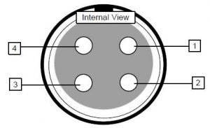
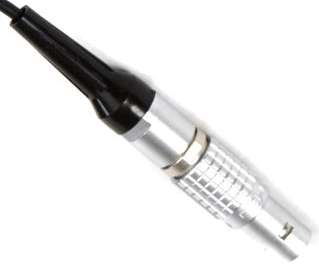
Pin1 – ground
Pin 2 – bias 9v +Ve
Pin 3 – signal & bias 9v +Ve
Pin 4 – signal
To wire a 2-wire condenser microphone use:
Pin 1 – ground, Pin 3 – signal & bias +Ve Pins 2 & 4 not connected
Trantec 4 Pin Mini XLR Connectors
Trantec Series 5 systems use a 4 pin mini XLR connector
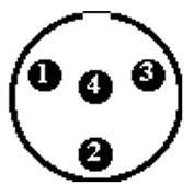

Pin 1 – ground
Pin 2 – bias 5v +Ve
Pin 3 – signal Hi-Z
Pin 4 – signal AF load resistor
To wire a 2-wire condenser microphone use:
Pin 1 – ground, link pins 3 & 4 – signal AF & bias +Ve and add a 10 KV bias between pins 2 & 4
(or some websites say use Pin 1 – ground, Pin 2 – signal AF & bias +Ve, Pins 3 & 4 should be linked)
Trantec and IMG Stageline 3.5mm Jack Connectors
Trantec S4 systems, Sennheiser, IMG Stageline TXS-600 range and some other wireless mic systems use a locking 3.5mm screw fit jack connector. The lapel microphone usually supplied with these systems is the LP2 – non locking standard 3.5mm connectors will work with these systems

Tip – signal & bias +Ve
Ring and sleeve – ground
To wire a 2-wire condenser microphone use:
Ring & sleeve – ground, tip signal & bias +Ve
IMG Stageline 3 Pin Mini XLR Connectors
IMG Stageline have traditionally used 3 pin mini XLR connectors on their wireless microphone transmitters – IMG Stageline also use various versions of locking 3.5mm jack connectors on some of their range
Gemini, AKG, Nady & Samson use the same 3 pin mini XLR connectors wired the same as IMG Stageline
Pin layout of the 3 pin mini XLR connector used on many IMG Stageline belt-pack wireless mic transmitters
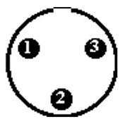

Pin 1 – ground
Pin 2 – mic signal
Pin 3 – bias voltage +Ve
To wire a 2-wire condenser microphone use:
Pin 1 – ground, Pin 2 – signal & bias +Ve, link pins 2 to 3 with 3K3 to 6K8 resistor
Audio Technica HRS Connectors
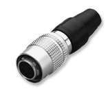
Audio-Technica have traditionally used Hirose HRS connectors on their wireless microphone transmitters but, for a short time, they did use mini DIN connectors
Pin layout of the HRS connector used on Audio-Technica belt-pack wireless mic transmitters
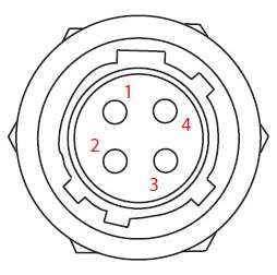
Pin 1 – ground
Pin 2 – line or instrument signal
Pin 3 – microphone signal
Pin 4 – bias +Ve
To wire a 2-wire condenser microphone use:
Link pins 1 & 2 – ground, link pins 3 & 4 signal & bias +Ve
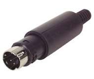
Audio Technica 4 Pin Mini DIN Connectors
Pin layout of the 4 pin mini DIN connector used on some early Audio-Technica belt-pack wireless microphone transmitters
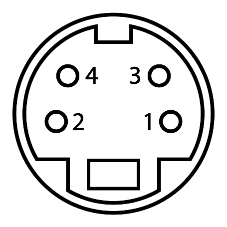
Skirt / Body – ground
Pin 1 – microphone signal
Pin 3 – bias +Ve
To wire a 2-wire condenser microphone use:
Link pins 1 & 3 – signal & bias +Ve and connect the ground screen to the skirt / body of the connector
XLR Connectors
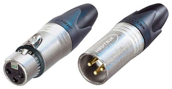
XLRs are the public address and PA sound system industry standard microphone connectors, robust and relatively simple to install – there are a number of ways in which these 3 pin connectors can be wired
For BALANCED operation
- Pin 1 connects to the screen (signal earth)
- Pin 2 connects to signal + (signal live)
- Pin 3 connects to signal – (signal return)
A balanced microphone will allow cable runs of up to 100m without any significant loss of performance
For balanced operation use twin core screened microphone cable
For UNBALANCED operation
- Pins 1 & 3 connects to the screen (signal earth)
- Pin 2 connects to signal + (signal live)
An unbalanced microphone can only be used up to about 10 meters away from the amplifier. Any more than this and noise problems become apparent
For unbalanced operation use single core screened microphone cable
To UNBALANCE a BALANCED XLR lead
- Connect pin 1 to pin 3 in the male XLR plug that is on the amplifier or mixer end of the lead
The 3 pin numbers are identified on the XLR plug and an easy way to remember how they should be wired is:
- X = Earth – Pin 1
- L = Live – Pin 2
- R = Return – Pin 3
Speakon Connectors
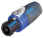
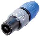
Neutrik Speakons and similar speaker connectors are the public address and PA sound system industry standard loudspeaker connectors, robust and relatively simple to install – there are a number of ways in which these 2 and pin connectors can be wired and used
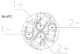 For LOW IMPEDANCE operation
- Pin 1- connects to loudspeaker – or common
- Pin 1+ connects to loudspeaker +
- Pin 2- is not used
- Pin 2+ is not used
For 100V LINE operation
- Pin 1- is not used
- Pin 1+ is not used
- Pin 2- connects to loudspeaker – or common
- Pin 2+ connects to loudspeaker +
For BI-AMPED LOW IMPEDANCE operation
- Pin 1- connects to bass loudspeaker – or common
- Pin 1+ connects to bass loudspeaker +
- Pin 2- connects to treble loudspeaker – or common
- Pin 2+ connects to treble loudspeaker +
To connect / plug-in
- An electrical connection between the Speakon connector (on the end of the cable) and Speakon input socket (on the loudspeaker or amplifier etc.) is not established until the Speakon connector locks into place
- Insert the Speakon connector (plug) into the socket on the amplifier or loudspeaker – the plug will only insert if correctly aligned with the socket
- Twist the Speakon connector clockwise until it engages
To Remove / disconnect
- To remove the plug from the socket you must slide (pull) the release lever towards the cable coming from the plug and then twist the plug anti-clockwise to disengage from the socket
- Now remove the plug from the socket
Phono Connectors
RCA phono connectors are popular audio connector used on auxiliary inputs & booster / slave inputs and outputs, also commonly used on mixers, CD and tape players etc. They are wired using single core screened cable
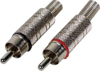
RCA Phono Connectors
Jack Connectors
There are two versions of 0.25″ Jack connector in common use, 2 pole mono and 3 pole stereo. The stereo plug is used for balanced microphones and audio uses the following pin connections
TIP – Signal +
RING – Signal –
SLEEVE – Screen / ground
For unbalanced operation the RING & SLEEVE should be joined
The 2 pole mono jack plug can only be used for unbalanced microphones as follows
TIP – Signal +
SLEEVE – screen / ground
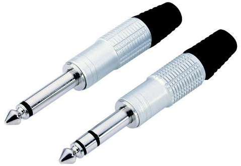
2 pole mono and 3 pole stereo 0.25″ jack connectors
DIN Connectors
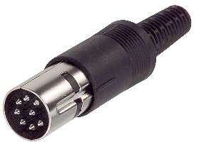
DIN connectors are no longer in common use – however they may be used by microphone priority circuits and on inputs that require various switching and voltage functions. Din connectors are available with varying pin layouts
Attenuator Pad for Mics and Wireless Mic Receivers
Pads or attenuators are often needed to connect a wireless microphone receiver to over sensitive amplifier, PA sound system or mixer inputs. The mic pad will reduce the signal level so that the sound is less distorted and that the operator has more effective control over the volume
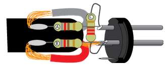
18.5db balanced mic pad attenuator
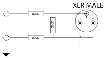
For unbalanced use replace 820Ω resistor in the signal line with 1600Ω (1K6) resistor, connect the 220Ω resistor between signal and earth and do not use a resistor in earth / ground line
If you require less attenuation reduce the 820Ω resistors to 390Ω each for a 14db balanced mic pad
For ease, mount the three resistors in the male XLR connector that plugs into the amplifier or mixer
Stereo Volume Control
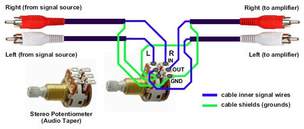
Often you need to reduce the volume between a mixer and an amplifier or allow the user just one level control to adjust the volume of the sound system – a twin ganged stereo 10kΩ logarithmic potentiometer will usually do the trick
100v Line Speaker Isolation Switch
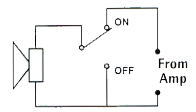
In to order to ensure complete isolation of a loudspeaker with absolutely no audio breakthrough it is necessary to use the circuit shown below. The loudspeaker will not only be isolated from the amplifier output but will also be shorted to itself when in the ‘off’ condition thus excluding any possibility of audio or noise breakthrough
Extend a 100v Line PA Sound System
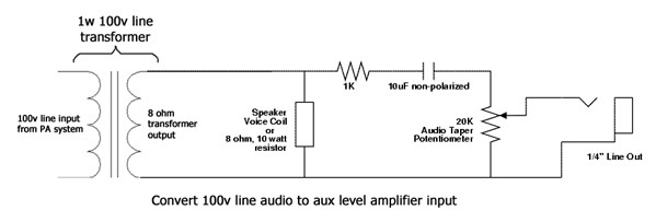
Take a feed from a loudspeaker to extend a 100v line PA sound system to extra amplifier(s) via a small 1w 100v line transformer
Phantom Power for Condenser Microphones
Phantom Power is a DC voltage sent via a balanced microphone cable to power a microphone or peripheral device such as a DI box etc. It is standard on most professional audio equipment, public address and PA sound systems
It is used most commonly with condenser microphones, but is sometimes used to power DI boxes and effects pedals.
Phantom power is usually 48 volts but can be as low as 9v and up to 52v DC
If pre-amps or mixer don’t feature phantom power it can be provided by a separate phantom adapter connected between the microphone and the mixer or amplifier input
You can add phantom power for condenser microphones and peripherals to mixers and pre-amps using the existing balanced microphone inputs on those devices
Most condenser microphones will accept a voltage between plus 12v and plus 52v DC on pins 2 and 3 on the XLR connector with 0v / ground on pin 1
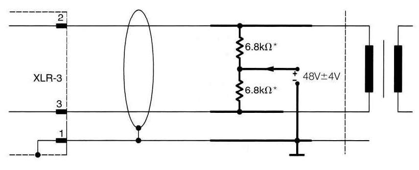
Phantom power added to a standard transformer balanced input
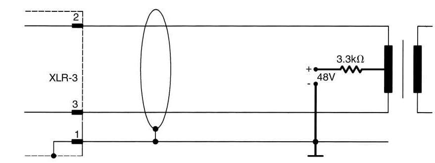
Phantom power added to a balanced input with a centre tapped transformer
When adding phantom power to a balanced mixer or pre-amp input you must use a fully regulated and well smoothed 12v to 52v DC power supply and you must ensure that DC blocking capacitors protect the mixer input as shown on the top diagram above. Pins 2 and 3 of the XLR must be + positive with 0v – ground on pin 1
Phantom Power and Wireless Microphone Receivers
Many wireless microphone receivers are not protected from having phantom power connected to their balanced line audio outputs
By connecting a wireless mic receiver to a mixer or amplifier which has phantom power selected can often damage your receiver in moments
You can help prevent this damage by having two 2.2mfd (2u2) 63v polarized capacitors in your XLR lead between the receiver and the mixer or amplifier. Taking care to ensure that the capacitors are the correct way round in series with the signals on each of pins 2 and pins 3 of your XLR lead
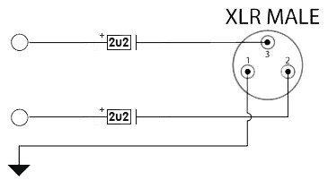
The positive of the capacitor should connect to the receiver and the negative of the capacitor should connect to the mixer or amplifier
Connecting a Stereo Source to a Mono Input
Stereo outputs from CD and media players etc. can be easily converted to mono to connect to the amplifier or mixer auxiliary input using the circuit shown. Resistor values of 4.7kΩ/0.25w have proved to be successful for this application

Wireless Mic Aerial Lengths
The length of wireless receiving and transmitting aerials is critical and the following nominal values should be used when replacing broken or missing 1/4 wavelength aerials on wireless microphones
VHF – 173.800 to 175.000 MHz – 40.75cm (16″)
UHF Ch. 38 – 606.000 to 614.000 MHz – 10.25cm (4″)
UHF Ch. 46 to 48 – 672.000 to 696.975 MHz – 9cm (3.5″)
UHF Ch. 69 – 854.000 to 862.900 MHz – 8.25cm (3.25″
UHF Ch. 70 – 863.000 to 865.000 MHz – 8.25cm (3.25″)
Double the length for 1/2 wavelength aerials
Mains & 100v Line Cable Colour Codes
In the UK we use the following configuration for our 230v AC mains plug wiring – EU colour codes are the same as the UK
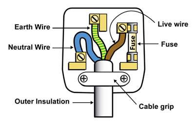
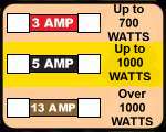
Standard 1″ cartridge fuses are used in the UK – use the lowest value that is suitable for your appliance
Loudspeaker Cable
100v line loudspeakers cable colour codes and cable sizes
- Colour codes used for 100v line speaker cable can vary – in the UK either red and black or brown and blue are used but USA favours black and white
- When installing a 100v line system, it is important that the correct size of cable is used to connect the speakers to the amplifier. Shorter runs may use 0.75mm² (6a) 2 core, twin sheathed flex whereas longer runs may require 1.5mm² (15a) 2 core, twin sheathed flex
- As the voltage on the line can approach 100 volts, installation must follow best practice with double insulated cable being used
- Cable runs should be kept away from any potential source of interference such as 3 phase mains, data, telecom cables etc.
- 100v Line Systems must always be wired in parallel
- The total loudspeaker load presented to the amplifier must not exceed the rated output of the amplifier or damage to the amplifier will result
- Horn speakers are typically used in noisy environments, outdoors or areas that are quite large in size. The main disadvantage with this type of speaker is the narrow frequency response making music reproduction difficult
- It is important to keep all 100v line loudspeakers connected ‘in phase’ – that is all Live / Hot connections on the loudspeakers should be connected together to one side of the amplifier’s 100v line output. This will ensure that the sound system works efficiently and that the best possible sound quality is reproduced by the sound system
Low Impedance
Some amplifiers have the facility for connection of low impedance loudspeakers. Low impedance installations require heavy cable feeding the loudspeakers to minimise losses and short cable runs of no more than 20 to 25m are recommended. Where it is intended to use multiple low impedance speakers to cover an area, the speakers must be wired in a series/parallel arrangement in such a way as to present the correct load to the amplifier
- The total loudspeaker load impedance presented to the amplifier must never be below the rated amplifier impedance of the amplifier or damage will result
- To avoid damage to the speakers the total wattage of the speaker driver units should be at least 30% higher than the rated power output of the amplifier
- You must never mix 100v line and low impedance speakers on the same system
Correct Microphone Handling
Remember – you must still project your voice when using any sort of microphone amplification system
and ALWAYS use the microphone from a position behind the loudspeakers


 Shipping from the EU & Third Party Depots